These are my computer-networking notes, cleaned up into three posts. This one covers the basics and the bottom two layers: how devices are wired together and how a frame gets from one to the next. Part Two is the network and transport layers (IP, routing, TCP and UDP), and Part Three is the layers above them, DNS, DHCP and the everyday questions and commands.
A computer network is a collection of interconnected devices that exchange data and share resources.
Basics
Types of network topology
A topology is the shape of the connections between devices.
1. Point to point
Two devices joined by one dedicated link.
flowchart LR
    X[Device X] <-->|dedicated link| Y[Device Y]
    classDef gateway fill:#EDE9FE,stroke:#7C3AED,color:#4C1D95,stroke-width:2px
    class X,Y gateway
- Advantages: efficient, because devices talk directly; more secure, because no intermediate device can be compromised; and simple to configure, with almost nothing to manage.
- Disadvantages: does not scale, since every new device needs its own links, which is slow and expensive to add; each device has to be maintained separately; and there is no redundancy, so a failed link or an offline device breaks the connection.
2. Bus
Every device hangs off one shared backbone cable, with a terminator at each end.
flowchart TB
    N1[Node 1] --- Bus
    N2[Node 2] --- Bus
    Bus["terminator ■━━━━━━━━━━━━ shared backbone cable ━━━━━━━━━━━━■ terminator"]
    Bus --- N3[Node 3]
    Bus --- N4[Node 4]
    classDef store   fill:#CFFAFE,stroke:#0891B2,color:#164E63,stroke-width:2px
    classDef gateway fill:#EDE9FE,stroke:#7C3AED,color:#4C1D95,stroke-width:2px
    class Bus store
    class N1,N2,N3,N4 gateway
- Advantages: the simplest way to connect computers or peripherals in a line. It works well for a small network, needs less cable than a star, and devices can be added or removed without affecting the others. It is the cheapest topology compared with mesh and star, and it is easy to understand and to extend by joining two cables.
- Disadvantages: not suited to large networks. When the whole network goes down the fault is hard to find, and troubleshooting a single device is hard. Both ends of the backbone need terminators, every added device slows the network, and packet loss is high. It is slower than other topologies, and if the backbone is damaged the whole network fails or splits in two.
- Ethernet LANs on a bus share the medium through MAC (media access control) protocols such as TDMA, pure ALOHA, slotted ALOHA and CDMA, covered in the data-link section below.
3. Ring
Each device connects to the next, and the last back to the first. Data travels one way round.
flowchart LR
    S1[Station 1] --> S2[Station 2] --> S3[Station 3] --> S4[Station 4] --> S1
    classDef gateway fill:#EDE9FE,stroke:#7C3AED,color:#4C1D95,stroke-width:2px
    class S1,S2,S3,S4 gateway
- Advantages: data flows in one direction, so collisions are rare. Workstations can be added without hurting performance. Every station has equal access without a controlling server. It is cheap to install and extend. Under heavy traffic it outperforms a bus, because access is by token passing: only the station holding the token transmits. It is easy to manage and orderly.
- Disadvantages: in a one-directional ring the token has to pass through every node, so one station going down takes the whole network down. It is slower than a bus under light load and more expensive. Adding or removing a node is difficult and disrupts the network, and the ring is hard to troubleshoot. Every computer must be on for all of them to communicate, everything depends on one cable, and it does not scale.
4. Star
Every device connects to a central hub or switch.
flowchart TD
    Hub[Hub or switch]
    Hub --- N1[Node 1]
    Hub --- N2[Node 2]
    Hub --- N3[Node 3]
    Hub --- N4[Node 4]
    Hub --- N5[Node 5]
    classDef warn    fill:#FEF3C7,stroke:#D97706,color:#78350F,stroke-width:2px
    classDef gateway fill:#EDE9FE,stroke:#7C3AED,color:#4C1D95,stroke-width:2px
    class Hub warn
    class N1,N2,N3,N4,N5 gateway
- Advantages: reliable, since one failed cable or device leaves the rest working. No collisions between devices on their own links, so it performs well. Each device needs only one port and one link to the hub, so N devices need N cables; it is easy to set up and robust. Faults are easy to find because each link is identifiable, and devices can be connected or removed without disrupting the network.
- Disadvantages: needs more cable than a bus. The central device is a single point of failure: if the hub or switch goes down, nothing attached to it can communicate. That central hardware adds cost, needs more resources and regular maintenance, and caps the network’s performance.
- Ethernet LAN protocols such as CSMA/CD (carrier sense multiple access with collision detection) are used here.
- A star forms a local area network (LAN).
5. Mesh
Devices link directly to many, or all, of the others.
flowchart LR
    A[A] --- B[B]
    A --- C[C]
    A --- D[D]
    A --- E[E]
    B --- C
    B --- D
    B --- E
    C --- D
    C --- E
    D --- E
    classDef gateway fill:#EDE9FE,stroke:#7C3AED,color:#4C1D95,stroke-width:2px
    class A,B,C,D,E gateway
- Types:
- Full mesh: every node connects to every other, so each of the n nodes has n − 1 links and the network needs n(n − 1)/2 links in total (10 for the five nodes above). Very redundant, expensive, and typical of network backbones.
- Partial mesh: not every pair is connected. More practical and cheaper; a common design uses a full-mesh backbone with the outer networks attached by partial mesh.
- Advantages: one failed device does not break the network. Each link is a dedicated point-to-point connection, so there is no shared traffic problem. Faults are easy to locate. There are many paths to every destination, so it is highly redundant and keeps delivering data through failures. Links are private, so it is secure. New devices do not disrupt traffic, and there is no central authority.
- Disadvantages: costlier than star, bus or point to point, and very hard to install. Every node must stay powered and share the load, so power use is higher. It is complex, many links are redundant, each node adds cost, and maintenance is demanding.
- Protocols used include AHCP (Ad Hoc Configuration Protocol) and DHCP.
6. Tree
A combination of bus and star: star networks hanging off a hierarchy of hubs.
flowchart TD
    C[Central hub] --- S1[System 1]
    C --- S2[System 2]
    C --- H1[Secondary hub]
    C --- H2[Secondary hub]
    H1 --- S3[System 3]
    H1 --- S4[System 4]
    H1 --- S5[System 5]
    H2 --- S6[System 6]
    H2 --- S7[System 7]
    H2 --- S8[System 8]
    classDef warn    fill:#FEF3C7,stroke:#D97706,color:#78350F,stroke-width:2px
    classDef gateway fill:#EDE9FE,stroke:#7C3AED,color:#4C1D95,stroke-width:2px
    class C,H1,H2 warn
    class S1,S2,S3,S4,S5,S6,S7,S8 gateway
7. Hybrid
Two or more topologies joined together, here a star linked to a ring.
flowchart LR
    subgraph Star
        Hub[Hub] --- Y1[System 1]
        Hub --- Y2[System 2]
        Hub --- Y3[System 3]
        Hub --- Y4[System 4]
    end
    subgraph Ring
        R1[Station 1] --> R2[Station 2] --> R3[Station 3] --> R4[Station 4] --> R1
    end
    Hub --- R2
    classDef warn    fill:#FEF3C7,stroke:#D97706,color:#78350F,stroke-width:2px
    classDef gateway fill:#EDE9FE,stroke:#7C3AED,color:#4C1D95,stroke-width:2px
    class Hub warn
    class Y1,Y2,Y3,Y4,R1,R2,R3,R4 gateway
Types of network
- PAN (personal area network)
- Connects a person’s own electronic devices. It can be wired, or wireless (WPAN). It is easy to use, portable and secure, but its range is short, data transfer is slow, and radio signals can interfere with it.
- Range: a few metres, typically up to about 10 m.
- Bluetooth and infrared (IR) are the common examples.
- LAN (local area network)
- Connects computers and workstations in a small area. It is fast, private, and works over several kinds of transmission medium, but it costs money to set up, is limited in size, and carries privacy and data-security risks.
- Much faster than a WAN, around 100 Mbps.
- Range: a single building up to a small area such as a campus.
- Example: in an office, employees’ computers join a LAN to share printers and exchange information inside the building.
- MAN (metropolitan area network)
- Connects several LANs across a city, providing high-speed data and internet access, usually over optical fibre. It allows resource sharing, fast connectivity and central management, but faces security threats, scaling limits and high cost. A MAN can be wired or wireless, serve many industries, and connect to other networks.
- Range: a city or metropolitan area, several kilometres across.
- Examples: a network linking the buildings of a large university, or a cable TV network.
- WAN (wide area network)
- Covers a large geographical area and connects LANs and MANs. It has broad reach, high capacity, uses public carriers and shares resources, but suffers congestion, low fault tolerance, noise and errors, and is slower than a LAN.
- Range: across cities, countries and continents.
- Example: the internet, which connects networks across the globe.
The OSI and TCP/IP models
The rest of the series walks the layers from the bottom up. The OSI model has seven layers; TCP/IP, the model the internet actually runs on, folds them into four or five. The notes follow OSI’s names and put session, presentation and application together at the top, as TCP/IP does.
| OSI layer | TCP/IP layer | Unit of data | Addresses by | Typical devices and protocols |
|---|---|---|---|---|
| 7. Application | Application | Data / message | – | HTTP, DNS, DHCP, SMTP, FTP, SSH |
| 6. Presentation | Application | Data | – | TLS/SSL, encoding, compression |
| 5. Session | Application | Data | – | RPC, session management |
| 4. Transport | Transport | Segment (TCP) / datagram (UDP) | Port number | TCP, UDP |
| 3. Network | Internet | Packet | IP address | Router, IP, ICMP, ARP, OSPF, BGP |
| 2. Data link | Network access (link) | Frame | MAC address | Switch, bridge, NIC, Ethernet |
| 1. Physical | Network access (link) | Bit | – | Hub, repeater, cables |
1. The physical layer
Network devices
1. Repeater
- Works at the physical layer.
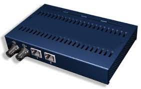
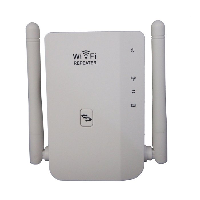
- A two-port device that amplifies and regenerates a weak or corrupted signal. Its job is to extend how far a signal travels on the same network before it becomes too weak: it copies the signal bit by bit and sends it on at full strength.
2. Hub
- Works at the physical layer.
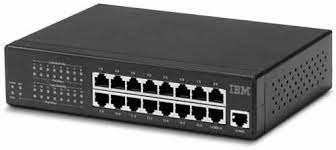
- A multi-port repeater at the centre of a star topology. It connects the cables from several devices and sends every incoming packet to every port, with no filtering. All its devices therefore share one collision domain.
- A collision domain is a part of the network where devices compete for the medium, so two transmitting at once collide. Every device in it has to listen to every message whatever its destination, and in half-duplex mode they wait and retransmit. A hub has no intelligence to route packets, so it is inefficient and wasteful.
- Types of hub:
- Active hub: acts as a repeater and a wiring centre, and boosts the signal.
- Passive hub: relays signals without cleaning or boosting them.
- Intelligent hub: adds remote management, flexible data rates, traffic monitoring and per-port configuration.
3. Bridge
- Works at the data-link layer.
- A repeater that can also filter traffic by MAC address. It is a two-port device that connects two LANs running the same protocol.
- Types:
- Transparent bridges: the stations do not know the bridge exists. They work through bridge forwarding and bridge learning: the bridge learns which MAC addresses sit on which side and forwards frames only when needed.
- Source routing bridges: the sending station decides the route, and each frame carries the route to follow. Stations find routes by sending discovery frames that spread through the network.
flowchart LR
    subgraph L1[LAN 1]
        P1[Desktop] ~~~ P2[Laptop] ~~~ P3[Printer]
    end
    subgraph L2[LAN 2]
        Q1[Desktop] ~~~ Q2[Desktop] ~~~ Q3[Laptop]
    end
    L1 <-->|frames filtered by MAC| Br[Bridge] <--> L2
    classDef warn    fill:#FEF3C7,stroke:#D97706,color:#78350F,stroke-width:2px
    classDef gateway fill:#EDE9FE,stroke:#7C3AED,color:#4C1D95,stroke-width:2px
    class Br warn
    class P1,P2,P3,Q1,Q2,Q3 gateway
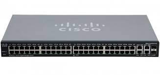
4. Switch
- Works at the data-link layer.
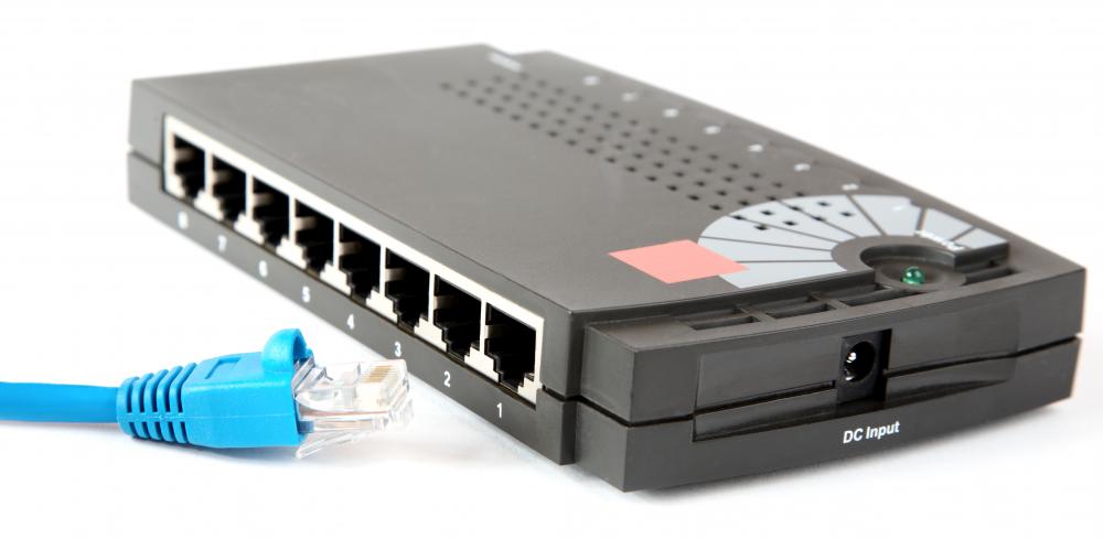
- A multi-port bridge with buffers. It checks frames for errors and forwards only good frames, and only to the port the destination is on. Each port is its own collision domain, but all ports stay in the same broadcast domain.
- A broadcast domain is the logical area in which a broadcast reaches every device. Broadcasts there cause congestion and eat everyone’s bandwidth, often called LAN congestion.
-
Types of switch:
Type Description Unmanaged Plug and play, no configuration. For small networks or to extend a larger one. Managed Configurable: VLANs, QoS, link aggregation. For larger networks with central management. Smart Some managed features, easier to set up. For small to medium networks. Layer 2 Works at the data-link layer, forwarding within one network segment. Layer 3 Works at the network layer, routing between segments. For larger networks. PoE Power over Ethernet: supplies power to devices over the data cable. Gigabit Supports gigabit Ethernet speeds. Rack-mounted Built for server racks, in data centres and large networks. Desktop Small, for desks and small offices. Modular Takes add-on modules, so it can be expanded or customised. For large networks and data centres.
5. Router
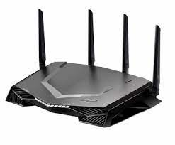
- A network-layer device that forwards packets by IP address. It connects LANs and WANs and decides where each packet goes using a routing table that it keeps up to date. A router separates broadcast domains.
| Device | Separates collision domains | Separates broadcast domains |
|---|---|---|
| Hub / repeater | No | No |
| Switch / bridge | Yes | No |
| Router | Yes | Yes |
How the devices combine in a network:
flowchart TD
    R[Router] --> S1[Switch 1]
    R --> S2[Switch 2]
    S1 --> HA[Hub A]
    S2 --> HB[Hub B]
    HA --> PA1[PC]
    HA --> PA2[PC]
    HB --> PB1[PC]
    HB --> PB2[PC]
    PA2 --> Br[Bridge]
    Br --> PC1[PC]
    Br --> PC2[PC]
    Br --> PC3[PC]
    classDef gateway fill:#EDE9FE,stroke:#7C3AED,color:#4C1D95,stroke-width:2px
    classDef service fill:#D1FAE5,stroke:#059669,color:#065F46,stroke-width:2px
    classDef warn    fill:#FEF3C7,stroke:#D97706,color:#78350F,stroke-width:2px
    classDef flow    fill:#F1F5F9,stroke:#475569,color:#0F172A,stroke-width:2px
    class R gateway
    class S1,S2 service
    class HA,HB,Br warn
    class PA1,PA2,PB1,PB2,PC1,PC2,PC3 flow
6. Gateway
- Works at the network layer (layer 3) or the application layer (layer 7).
- At layer 3 it connects two networks that use different networking models. It acts as a messenger that interprets and passes data between the systems, which is why it is also called a protocol converter. Gateways are usually more complex than switches or routers.
- At layer 7 it is an entry or exit point that converts between applications or services using different protocols or data formats. These are called application gateways or proxy servers.
flowchart LR
    subgraph N1["Network 10.0.0.0/8"]
        A1[Server] ~~~ A2[PCs]
    end
    subgraph N2["Network 20.0.0.0/8"]
        B1[Server] ~~~ B2[PCs]
    end
    N1 <--> G[Gateway<br/>protocol converter] <--> N2
    classDef warn    fill:#FEF3C7,stroke:#D97706,color:#78350F,stroke-width:2px
    classDef gateway fill:#EDE9FE,stroke:#7C3AED,color:#4C1D95,stroke-width:2px
    class G warn
    class A1,A2,B1,B2 gateway
7. Brouter
- A bridging router: it combines a bridge and a router. It can route packets between networks and filter LAN traffic, at either the data-link layer or the network layer.
8. NIC
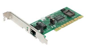
- The network interface card is a layer 2 (data link) adapter that connects a computer to the network. It carries a unique ID, the MAC address, and a cable interface (an Ethernet RJ-45 port). It lets the computer join a LAN and talk to the router or modem at the physical and data-link layers.
Transmission media
A transmission medium is the physical path between the transmitter and the receiver.
1. Guided media
Also called wired or bounded media: fast and secure over shorter distances.
- Twisted pair cable, the most widely used medium.
-
UTP (unshielded twisted pair): two insulated copper wires twisted together. Cheap, easy to install and fast, but picks up external interference. Used in telephony and LANs.
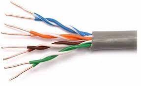
UTP: four twisted pairs, no shielding. -
STP (shielded twisted pair): adds a copper braid or foil shield that blocks external interference. Performs better at higher data rates and eliminates crosstalk, but is harder to make and install, more expensive and bulkier. Used where extra shielding is needed, including cold climates.
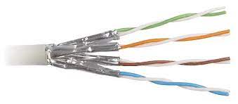
STP: each pair wrapped in foil.
-
-
Coaxial cable: a centre conductor and an outer conductor sharing one axis, inside a plastic jacket. High bandwidth and good noise immunity. Used for cable TV, computer networks such as early Ethernet, and radio-frequency transmission. Easy to install and extend, but one failed cable can disrupt the network. From the outside in: protective plastic jacket, braided metal conductor (the shield), insulator, copper centre conductor.
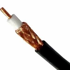
Coaxial cable, cut away. 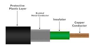
The four layers of a coaxial cable. -
Optical fibre cable: a core and cladding of glass or plastic that carry light. Very high capacity and bandwidth, light, low attenuation, immune to electromagnetic interference and resistant to corrosion. On the other hand it is hard to install and maintain, expensive and fragile. Used in medical instruments, aerospace data links, internet backbone cables, and industrial and automotive lighting. From the outside in: outer jacket, strength member, coating, cladding, core.
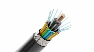
A multi-fibre cable, cut open. 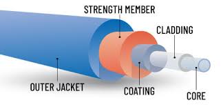
The layers of a single optical fibre.
2. Unguided media
Also called wireless or unbounded media: electromagnetic signals sent through the air. They cover longer distances but are less secure than wired links.
- Radio waves: easy to generate and able to pass through buildings. Used by AM and FM radio and cordless phones, split into terrestrial and satellite. Frequency range 3 kHz to 1 GHz. Wi-Fi and Bluetooth are examples.
- Microwaves: line-of-sight transmission, so the sending and receiving antennas must be aligned, and the distance a signal reaches grows with antenna height. Frequency range 1 GHz to 300 GHz. Used mainly for mobile phones and television distribution.
- Infrared: short-range only. It cannot pass through obstacles, which also keeps devices from interfering with each other. Frequency range 300 GHz to 400 THz. Used by TV remotes, wireless mice and keyboards, and printers.
Transmission modes
Also called communication modes: which way data can flow between two devices.
1. Simplex. One direction only: one device transmits, the other only receives. Cheap, reliable, and needs no coordination, but there is no way to reply or confirm the data.
sequenceDiagram
    participant A as Device A
    participant B as Device B
    A->>B: data (one direction only)
    A->>B: data
2. Half duplex. Both devices can transmit and receive, but not at the same time. It allows two-way communication and is more efficient than simplex, but it is less reliable, adds delay, and the devices have to take turns.
Channel capacity = bandwidth × propagation delay
sequenceDiagram
    participant A as Device A
    participant B as Device B
    Note over A,B: A's turn: A sends, B receives
    A->>B: data
    Note over A,B: B's turn: B sends, A receives
    B->>A: data
3. Full duplex. Both sides transmit and receive at the same time, which suits real-time applications. The most efficient and most reliable, but also the most expensive and complex, and not every kind of communication needs it.
Channel capacity = 2 × bandwidth × propagation delay
sequenceDiagram
    participant X as Device X
    participant Y as Device Y
    par at the same time
        X->>Y: transmit
    and
        Y->>X: transmit
    end
Functions of the physical layer
- Interface: defines the interface between devices and the transmission medium.
- Representation of bits: data here is a stream of bits, which must be encoded into signals. The layer defines the encoding, i.e. how 0s and 1s become signals.
- Data rate: defines the transmission rate in bits per second.
- Transmission mode: defines the direction of transmission: simplex, half duplex or full duplex.
- Line configuration: connects devices to the medium point to point or multipoint.
- Topology: devices are connected in some topology: mesh, star, bus, ring and so on.
Design issues in the physical layer
- The physical layer is about transmitting raw bits over a channel.
- The design issues are the electrical, mechanical and timing interfaces, and the physical medium below the layer.
- The core issue is making sure that a 1 bit sent from one side arrives as a 1 bit on the other, not as a 0.
Line configuration
A link is the path that carries data from one device to another. There are two kinds of connection:
- Point-to-point: a dedicated link between two devices, over wire, cable, microwave or satellite. Simple to set up and understand, so it is the conventional choice. Example: a remote control and a television.
- Multipoint (multidrop): two or more devices share one link, the shared channel. The link
is shared in one of two ways:
- Spatial sharing: several devices use the link at the same time.
- Temporal (time) sharing: devices take turns.
2. The data-link layer
Services the data-link layer provides
The data-link layer serves the network layer above it. It carries frames from the sending machine’s data-link layer to the receiving machine’s network layer. The actual path goes down through the physical layer and across the medium; the network layer sees a virtual path straight across to its peer, provided by the data-link protocol.
flowchart TB
    subgraph M1[Machine 1]
        direction TB
        U1[Upper layers] --- N1[Network] --- D1[Data link] --- P1[Physical]
    end
    subgraph M2[Machine 2]
        direction TB
        U2[Upper layers] --- N2[Network] --- D2[Data link] --- P2[Physical]
    end
    D1 -.->|virtual path| D2
    P1 ==>|actual path over the medium| P2
    classDef gateway fill:#EDE9FE,stroke:#7C3AED,color:#4C1D95,stroke-width:2px
    classDef service fill:#D1FAE5,stroke:#059669,color:#065F46,stroke-width:2px
    classDef flow    fill:#F1F5F9,stroke:#475569,color:#0F172A,stroke-width:2px
    class D1,D2 gateway
    class P1,P2 service
    class U1,U2,N1,N2 flow
Types of service:
- Unacknowledged connectionless: datagram-style delivery with no error or flow control. The source sends independent frames without acknowledgements, sets up no connection before or after, and makes no attempt to detect or recover lost frames. Ethernet works this way.
- Acknowledged connectionless: every frame is acknowledged individually, so the sender knows what arrived. Reliable, and used on unreliable channels such as wireless and Wi-Fi.
- Acknowledged connection-oriented: a connection is set up before data moves, and every frame is numbered, so delivery is guaranteed and in order.
Sub-layers of the data-link layer
- Logical link control (LLC): handles multiplexing and the flow of data between applications and services, and provides error messages and acknowledgements.
- Media access control (MAC): addresses frames and controls access to the physical medium.
Functions of the data-link layer
1. Framing
- A frame is the unit of transmission at the data-link layer: a distinguishable block of bits that carries error-checking codes, so delivery is organised and controlled.
- Problems in framing:
- Detecting the start of a frame: stations look for a special bit sequence, the start frame delimiter (SFD), that marks where a frame begins.
- Detecting the end of a frame: knowing when to stop reading.
- Handling errors: noise and transmission errors corrupt frames, so error detection such as the cyclic redundancy check (CRC) is needed to verify them.
- Framing overhead: headers and trailers use bandwidth that could carry data, which matters most for small frames.
- Framing incompatibility: devices and protocols that frame data differently can misread each other’s frames.
- Framing synchronisation: stations must agree on frame boundaries and timing to avoid collisions, which is hard in complex networks with varying load.
- Framing efficiency: good framing keeps overhead low and bandwidth and latency good.
- Types of framing:
- Fixed size: the frame’s length is its delimiter, so no explicit boundaries are needed. Small payloads waste space (internal fragmentation), which padding fills.
- Variable size: the end of one frame and the start of the next have to be marked. Two
ways:
- Length field: a field states the frame’s length. Used by Ethernet (802.3). The risk is that the length field itself gets corrupted.
- End delimiter (ED): a bit pattern marks the end of the frame. Used by Token Ring. The
risk is that the pattern also appears in the data, which is solved by stuffing:
- Character (byte) stuffing, for frames made of characters. If the data contains
the ED, an extra byte is stuffed in to mark it as data.
- Say ED =
$. A$in the data is escaped as\O$. - If the data contains
\O$, it becomes\O\O\O$: the$is escaped with\O, and the\Ois escaped with another\O. - It is costly and obsolete.
- Say ED =
- Bit stuffing:
- Say ED =
01111and the data is01111. - The sender stuffs a bit to break the pattern: after
0111it inserts a0, so the data goes out as011101. - The receiver sees
011101, removes the stuffed0, and reads the data. - Example: data
011100011110with ED0111. After every011the sender inserts a0, giving011010001101100, i.e.011010001101100.
- Say ED =
- Character (byte) stuffing, for frames made of characters. If the data contains
the ED, an extra byte is stuffed in to mark it as data.
2. Addressing
- The data-link layer puts the source and destination MAC (physical) addresses in each frame’s header, for node-to-node delivery.
- A MAC address is 48 bits (6 bytes), written like
00:1A:2B:3C:4D:5Eor00-1A-2B-3C-4D-5E. The first half identifies the manufacturer, the second half the device. - The IEEE keeps them unique by assigning blocks of addresses to manufacturers.
3. Error control
Error control makes sure frames arrive correctly: it detects lost or corrupted frames and has them retransmitted, through automatic repeat request (ARQ).
Error detection
Types of error. The same 8 bits sent, three ways to receive them:
| Error | Sent | Received | What changed |
|---|---|---|---|
| Single-bit | 10110011 |
10110111 |
one bit (bit 6, 0 → 1) |
| Multiple-bit | 10110011 |
10100111 |
two separate bits (bit 4, 1 → 0; bit 6, 0 → 1) |
| Burst | 10110011 |
11000111 |
a run of consecutive bits (bits 2 to 4) |
Error-detection methods:
1. Simple parity check (even parity).
- If the block has an odd number of 1s, append a 1; if even, append a 0.
- That makes the total number of 1s even, hence even parity.
- It cannot detect an even number of flipped bits, since those leave the count even.
flowchart LR
    D[Data 100011<br/>three 1s] --> P[Append parity bit 1] --> T[Send 1000111] --> R{Receiver: is the<br/>count of 1s even?}
    R -->|yes| OK([Accept data])
    R -->|no| NO([Reject data])
    classDef flow  fill:#F1F5F9,stroke:#475569,color:#0F172A,stroke-width:2px
    classDef warn  fill:#FEF3C7,stroke:#D97706,color:#78350F,stroke-width:2px
    classDef ok    fill:#DCFCE7,stroke:#16A34A,color:#14532D,stroke-width:2px
    classDef error fill:#FEE2E2,stroke:#DC2626,color:#7F1D1D,stroke-width:2px
    class D,P,T flow
    class R warn
    class OK ok
    class NO error
2. Two-dimensional parity. Parity bits are computed for each row, as in a simple parity check, and also for each column. Both go with the data, and the receiver recomputes and compares them.
For the data 10011001 11100010 00100100 10000100, arranged as rows:
| Row | Data | Row parity |
|---|---|---|
| 1 | 10011001 |
0 |
| 2 | 11100010 |
0 |
| 3 | 00100100 |
0 |
| 4 | 10000100 |
0 |
| Column parity | 11011011 |
0 |
Data sent: 100110010 111000100 001001000 100001000 110110110.
3. Checksum.
Sender:
- Divide the data into k segments of m bits.
- Add the segments using one’s-complement arithmetic (carries wrap around and are added back in).
- Complement the sum: that is the checksum, sent with the data.
Receiver:
- Add all received segments, checksum included, in one’s-complement arithmetic.
- Complement the sum.
- If the result is zero, accept the data; otherwise discard it.
Worked through with k = 4, m = 8 and the same data as above:
| Step | Sender | Receiver |
|---|---|---|
| Segments | 10011001 11100010 00100100 10000100 |
the same four, plus checksum 11011010 |
| Sum with carries wrapped | 00100101 |
11111111 |
| Complement | 11011010 = checksum |
00000000 |
| Result | send data + checksum | zero, so accept |
4. Cyclic redundancy check (CRC). The sender appends n zeros to the data, where the divisor (generator) has n + 1 bits, and divides by the generator using XOR (modulo-2) division. The n-bit remainder is the CRC, and it replaces the zeros. The receiver divides what it gets by the same generator; a zero remainder means no error was detected.
flowchart LR
    subgraph Sender
        direction TB
        A[Data, m bits<br/>+ n zeros] --> Div1[Divide by<br/>n+1-bit divisor] --> C[Remainder = CRC, n bits] --> Snd[Send data + CRC]
    end
    subgraph Receiver
        direction TB
        Rcv[Data + CRC] --> Div2[Divide by<br/>the same divisor] --> Z{Remainder<br/>zero?}
        Z -->|yes| Acc([Accept])
        Z -->|no| Rej([Reject])
    end
    Snd --> Rcv
    classDef flow  fill:#F1F5F9,stroke:#475569,color:#0F172A,stroke-width:2px
    classDef warn  fill:#FEF3C7,stroke:#D97706,color:#78350F,stroke-width:2px
    classDef ok    fill:#DCFCE7,stroke:#16A34A,color:#14532D,stroke-width:2px
    classDef error fill:#FEE2E2,stroke:#DC2626,color:#7F1D1D,stroke-width:2px
    class A,Div1,C,Snd,Rcv,Div2 flow
    class Z warn
    class Acc ok
    class Rej error
Worked example: message 1010000, generator x³ + 1 = 1001 (4 bits, so append 3 zeros).
| Step | Bits under the divisor | XOR with 1001 |
|---|---|---|
| 1 | 1010 |
0011 |
| 2 | 1100 |
0101 |
| 3 | 1010 |
0011 |
| 4 | 1100 |
0101 |
| 5 | 1010 |
0011 |
| Remainder | 011 |
The sender transmits 1010000 + 011 = 1010000011. The receiver divides 1010000011 by 1001
and gets remainder 000, so it accepts the data.
Error correction
Error correction lets the receiver fix errors itself, without a reverse channel to ask for a retransmission. Techniques:
- Hamming distance: to correct t errors, codewords must differ by a minimum Hamming distance of 2t + 1. That takes many redundant bits, so it is rarely used.
- XOR: split a packet into N chunks and also send the XOR of all of them, N + 1 chunks in total. If any one chunk is lost or corrupted, the receiver rebuilds it from the rest. With N = 4, that is 25% extra data, and one lost chunk out of four can be recovered.
- Chunk interleaving: data is cut into chunks written row by row, but packets are made by reading the chunks column by column, so every packet carries one chunk from several original packets. Lose a packet and each original packet is missing just one small chunk, which multimedia can usually tolerate.
Techniques for error control
1. Stop-and-wait ARQ.
Useful terms:
- Propagation delay: the time a packet takes to physically travel from one router to the next.
- Round-trip time (RTT): the time for a packet to reach the receiver plus the time for its acknowledgement to come back.
- Timeout (TO): usually set to 2 × RTT.
- Time to live (TTL): the notes give 2 × timeout, with a maximum of 255. In IP itself, TTL is an 8-bit hop count (maximum 255) that each router decrements, not a time.
Characteristics:
- The link is used as half duplex.
- It is the sliding-window protocol with a window size of 1.
- However many packets the sender has, it needs only two sequence numbers, 0 and 1.
How it works:
- Sender A sends a frame with sequence number 0.
- Receiver B replies with acknowledgement 1, the sequence number of the frame it expects next.
With a one-bit sequence number, sender and receiver each need a buffer for just one frame. When a frame or an acknowledgement is lost, the sender’s timeout fires and it resends; the sequence number lets the receiver spot and discard a duplicate.
sequenceDiagram
    participant A as Sender A
    participant B as Receiver B
    A->>B: Frame 0
    B->>A: Ack 1
    A->>B: Frame 1
    B->>A: Ack 0
    A-xB: Frame 0 (lost)
    Note over A: timeout: frame lost, A retransmits
    A->>B: Frame 0
    B->>A: Ack 1
    A->>B: Frame 1
    B-xA: Ack 0 (lost)
    Note over A: timeout: ack lost, A retransmits
    A->>B: Frame 1
    Note over B: duplicate frame, discarded
    B->>A: Ack 0
Advantages:
- Simple to implement in hardware and software, so cheap and efficient.
- Error detection through checksums or CRC.
- Reliable: every packet is acknowledged before the next is sent, so nothing is corrupted or reordered.
- Flow control: the receiver sets the pace, useful when its buffers or processing are limited.
- Backward compatible with many existing systems and protocols.
Disadvantages:
- Low efficiency: the sender sits idle waiting for acknowledgements, which is slow for large transfers.
- High latency for the same reason, which hurts real-time applications.
- Poor bandwidth use: only one packet is in flight at a time.
- Limited error recovery: a lost or corrupted packet is resent whole.
- Sensitive to channel noise: errors cause frequent retransmissions.
2. Sliding-window ARQ.
- Stop-and-wait gives error and flow control but performs badly because the sender waits. The sliding-window protocol fixes that by letting several packets be in flight at once.
- This is pipelining: a window of packets is sent without waiting for each acknowledgement. How many packets fit in one cycle follows from the transmission time and the propagation time. Pipelining keeps packets flowing and cuts idle time.
- Sliding window is the idea of picking the best window size; in practice it is implemented as two protocols:
Go-Back-N (GBN):
- The sender window (WS) is N, with N > 1 for pipelining.
- The receiver window (WR) is always 1.
- If a packet is lost, the sender goes back and resends everything from that packet on.
- Acknowledgements can be cumulative (one ack covers several packets: less traffic, less reliable) or independent (one ack per packet: more reliable, more traffic).
- It needs at least N + 1 sequence numbers so duplicates cannot be confused with new packets.
sequenceDiagram
    participant S as Sender (window of 4)
    participant R as Receiver (window of 1)
    S->>R: 0
    S->>R: 1
    S-xR: 2 (lost)
    S->>R: 3
    S->>R: 4
    S->>R: 5
    Note over R: 0 and 1 accepted. 3, 4, 5 discarded: 2 was expected
    Note over S: timeout on 2: go back and resend the window
    S->>R: 2
    S->>R: 3
    S->>R: 4
    S->>R: 5
Selective Repeat (SRP):
- A variation of Go-Back-N.
- Both sender and receiver keep a buffer, each with a window of a set size.
- Suited to unreliable links where retransmissions are common.
- Only the frames that need it are retransmitted, not the whole window, so it is more efficient.
- Needs a full-duplex link, since the receiver sends acknowledgements back while data flows.
- The sender can send new packets as long as they are within the window of unacknowledged packets.
- The sender resends an unacknowledged packet on a timeout or when it receives a NAK (negative acknowledgement).
- The receiver acknowledges every correct packet and holds them until they can be delivered in order.
sequenceDiagram
    participant S as Sender (window 2)
    participant R as Receiver (window 2)
    S->>R: Frame 0
    S->>R: Frame 1
    R->>S: ACK 2
    S-xR: Frame 2 (lost)
    S->>R: Frame 3
    Note over R: 3 buffered, 2 missing
    R->>S: NAK 2
    S->>R: Frame 2 (resent)
    Note over R: 2 and 3 delivered in order
4. Flow control
Flow control matches the sender’s speed to the receiver’s. The sender and receiver can transmit and process at different rates; flow control keeps the receiver from being overloaded and paces frames by the receiver’s acknowledgements.
Approaches:
- Feedback-based: the receiver sends feedback, and the sender sends more data according to the receiver’s processing status and acknowledgements.
- Rate-based: when the sender is faster than the receiver, a mechanism built into the protocol caps the rate, without any feedback from the receiver.
Techniques:
- Stop-and-wait flow control
- The message is split into frames; the receiver signals when it is ready; the sender waits for an acknowledgement before sending the next frame. One frame at a time. Inefficient when the propagation delay is longer than the transmission delay.
- Advantages: simple, and every frame is checked and acknowledged, so it is accurate.
- Disadvantages: slow, one frame at a time.
- Sliding-window flow control
- Reliable, in-order delivery where the sender can send several frames before any acknowledgement, which raises throughput. The receiver takes them one by one and acknowledges with the next frame number it expects.
- Advantages: faster and more efficient than stop-and-wait, with frames sent back to back.
- Disadvantages: more complex at both ends, and frames can arrive out of sequence.
5. Access control
When many stations share one channel, a multiple-access protocol decides who transmits when, so that simultaneous transmissions do not collide. It is like a teacher deciding which student answers next.
Types of multiple-access protocol
1. Random access.
- ALOHA (hello and goodbye in Hawaiian). Every station has equal priority and sends depending
on whether the medium is idle or busy. There is no fixed time to send and no fixed order of
stations.
- Pure ALOHA: a station sends and waits for an acknowledgement. If none arrives in time, it waits a random back-off time (Tb) and resends. Because stations wait different random times, a second collision becomes less likely.
- Slotted ALOHA: time is divided into slots and a station may only start sending at the beginning of a slot. Miss it and you wait for the next, which cuts collisions further.
-
CSMA (carrier sense multiple access): a station senses the medium before sending. If it is idle, the station transmits; if busy, it waits. Collisions still happen because of propagation delay: A starts sending, but before its signal reaches B, B senses an idle medium and starts too.
CSMA access modes:
- 1-persistent: if the channel is idle, send immediately; if not, keep sensing and send the moment it goes idle (with probability 1).
- Non-persistent: if the channel is idle, send; if not, check again after a random interval.
- p-persistent: if the channel is idle, send with probability p; with probability 1 − p, wait a slot and sense again, repeating until the frame is sent. Used in Wi-Fi and packet radio.
- O-persistent: stations have a fixed order of priority and each sends only in its own time slot when the medium is idle.
- CSMA/CD (collision detection): stations detect collisions while transmitting and stop. For that to work a frame must be long enough to still be sending when a collision comes back: the transmission time must be at least twice the maximum propagation delay. Slots lost to collisions are called contention slots. Used by classic (half-duplex, wired) Ethernet.
-
CSMA/CA (collision avoidance): used in wireless networks, where a station cannot reliably hear a collision while it transmits, because its own signal drowns out everyone else’s. Instead of detecting collisions, it works to avoid them:
- Interframe space (IFS): when the medium goes idle, the station waits a further period, the IFS, before sending. Stations with higher priority get a shorter IFS.
- Contention window: time is split into slots and a ready station waits a random number of them. Each time the medium is found busy, the window doubles; when it goes idle, the timer resumes.
- Acknowledgement: if no acknowledgement arrives within the timeout, the sender assumes the frame was lost and retransmits.
2. Controlled access. Stations consult one another to decide which one has the right to send. Only one node sends at a time, so messages on the shared medium never collide. Three methods:
- Reservation: stations reserve before sending. A fixed-length reservation interval is divided into slots, one per station, and a station announces its intent to send in its slot, so data then goes out in order with no collisions. Advantages: predictable performance, less contention, QoS support, efficient bandwidth use, good for multimedia. Disadvantages: depends on the reservation scheme working, wastes capacity under light load, and adds turn-around time.
- Polling: a controller asks each node in turn whether it has data, like a roll call, and exchanges data only with the node it has selected. Advantages: fixed access times and data rates, high efficiency, and priorities are possible. Disadvantages: high overhead, depends on the controller staying up, slow, can be biased in sharing the link, and wastes rate under light load.
- Token passing: stations form a logical ring and a token circulates among them in a set order. Only the station holding the token may send a frame; afterwards it passes the token on, and it waits for all N stations to have had their turn. The hard parts are duplicated or lost tokens and stations joining or leaving.
3. Channelisation.
- FDMA (frequency division multiple access): the bandwidth is divided into equal bands, one per station, with guard bands between them to prevent overlap, crosstalk and noise.
- TDMA (time division multiple access): the stations share the whole bandwidth but take turns in time slots. Each station must know its slot, which costs synchronisation bits in every slot, and guard times absorb propagation delay.
- CDMA (code division multiple access): all stations transmit at once over the whole channel, with no split in bandwidth or time. Each uses a different code, like people talking in a room in different languages without confusing each other.
- OFDMA (orthogonal frequency division multiple access): splits the bandwidth into many small subcarriers for better performance. Widely used in 5G. Efficient, fast and suited to multimedia, but complex to implement.
- SDMA (spatial division multiple access): uses multiple antennas to separate users by direction. Common in MIMO (multiple-input, multiple-output) wireless systems. It uses the frequency band well, improves signal quality and raises data rates, but is complex and needs accurate channel information.
In short: contention-based protocols such as CSMA listen before sending, with collision detection (CD) or collision avoidance (CA) added, while token passing hands out exclusive turns. Contention can waste bandwidth under load; token passing can use it more fully.
Ethernet
- The most widely used LAN technology, defined by IEEE 802.3.
- Works at the physical and data-link layers.
- Uses CSMA/CD to handle collisions and Manchester encoding (in classic 10 Mbps Ethernet). Current Ethernet runs at up to 100 Gbps and beyond.
- Advantages: fast (faster than wireless), energy efficient, good quality (resistant to noise), reliable (error detection), cheap, interoperable, secure (supports encryption and authentication), manageable, compatible, scalable, widely available, simple and standardised.
- Disadvantages: distance limits (100 m on twisted pair), shared bandwidth, security weaknesses, complexity, compatibility issues, cabling work, and physical limits on network design.
Ethernet (IEEE 802.3) frame format
| Field | Size | Purpose |
|---|---|---|
| Preamble | 7 bytes | Alternating 0s and 1s for bit synchronisation |
| Start frame delimiter (SFD) | 1 byte | 10101011: marks the start of the frame |
| Destination address | 6 bytes | MAC address of the destination |
| Source address | 6 bytes | MAC address of the sender (always unicast) |
| Length | 2 bytes | Length of the frame’s data; the field could express up to 65,534, but Ethernet caps data at 1,500 bytes |
| Data | 46–1,500 bytes | The payload, padded if under 46 bytes |
| CRC (frame check sequence) | 4 bytes | Checksum over destination, source, length and data, for error detection |
The Ethernet header is the 14 bytes from destination address to length. Related features:
- VLAN tagging: a 4-byte tag inserted after the source address splits one physical network into several virtual ones.
- Jumbo frames: frames with more than 1,500 bytes of payload, for higher throughput.
- EtherType: in Ethernet II framing the length field instead identifies the protocol in the payload, e.g. IP or ARP.
- Multicast and broadcast frames: Ethernet can address a group of devices, or all of them.
- Collision detection: half-duplex Ethernet uses CSMA/CD to detect and handle collisions.
An IEEE 802.3 Ethernet frame is 64 to 1,518 bytes, of which the data is 46 to 1,500 bytes. The preamble and SFD are not counted in that size.
VLAN
- A VLAN (virtual LAN) groups devices logically at layer 2. A switch then keeps each VLAN in its own broadcast domain, and inter-VLAN routing forwards packets between them. The result is smaller, more manageable sub-networks.
flowchart TD
    SW[Switch] --- W1[Workstation 1<br/>VLAN 1]
    SW --- W2[Workstation 2<br/>VLAN 1]
    SW --- W3[Workstation 3<br/>VLAN 1]
    SW --- W4[Workstation 4<br/>VLAN 2]
    SW --- W5[Workstation 5<br/>VLAN 2]
    W1 -.->|broadcast reaches VLAN 1 only| W2
    W1 -.-> W3
    classDef service fill:#D1FAE5,stroke:#059669,color:#065F46,stroke-width:2px
    classDef gateway fill:#EDE9FE,stroke:#7C3AED,color:#4C1D95,stroke-width:2px
    classDef flow    fill:#F1F5F9,stroke:#475569,color:#0F172A,stroke-width:2px
    class SW service
    class W1,W2,W3 gateway
    class W4,W5 flow
VLANs can also span switches, with a router joining them:
flowchart TD
    R[Router<br/>inter-VLAN routing] --- S1[Switch 1]
    R --- S2[Switch 2]
    S1 --- V1[VLAN 1: Manufacturing]
    S1 --- V2a[VLAN 2: Sales]
    S2 --- V3[VLAN 3: HR]
    S2 --- V2b[VLAN 2: Sales]
    classDef gateway fill:#EDE9FE,stroke:#7C3AED,color:#4C1D95,stroke-width:2px
    classDef service fill:#D1FAE5,stroke:#059669,color:#065F46,stroke-width:2px
    classDef flow    fill:#F1F5F9,stroke:#475569,color:#0F172A,stroke-width:2px
    class R gateway
    class S1,S2 service
    class V1,V2a,V3,V2b flow
- VLANs improve security and performance, simplify management, and add flexibility, cost savings and scalability: they separate traffic logically, cut broadcast traffic, allow dynamic configuration, reduce hardware, and segment the network.
- Key features: VLAN tagging to mark which VLAN a frame belongs to, VLAN membership to assign devices, VLAN trunking to carry several VLANs over one link, and VLAN management to configure and administer them.
- Types of link:
- Trunk link: every device on it must be VLAN-aware; frames carry a VLAN tag.
- Access link: connects VLAN-unaware devices to a VLAN-aware switch; frames are untagged.
- Hybrid link: both at once, carrying tagged and untagged frames, for VLAN-aware and VLAN-unaware devices.
- Advantages: better performance by cutting unnecessary broadcast and multicast traffic, grouping devices logically (by department, say), better security, more flexibility, lower cost since fewer routers are needed, and smaller broadcast domains that are easier to manage.
- Disadvantages: configuration and management complexity, limited scalability, limited security, limited interoperability, limited mobility, cost, and less visibility for monitoring and troubleshooting.
- Real-time uses: better VoIP quality, prioritised video conferencing, secure remote access, efficient cloud backup and recovery, prioritised gaming, and IoT security.
That is everything up to the frame. The next part lifts it into a packet and sends it across networks.
Next: IP addressing, routing, TCP and UDP: the network and transport layers